EXTOLL’s Chip-to-Chip (C2C) link serves to connect the eProcessor chip to other eProcessors or the companion FPGA. The eProcessor’s NoC can be extended to the companion FPGA via the C2C link using a crosspoint connection of the NoC. In the FPGA, the same NoC channels, using the same interface, are repeated allowing the link to act as a bridge to DDR4 memory, possibly PCIe and other I/O peripherals.
The C2C consists of four parallel bidirectional channels, as does the NoC. Each of these channels is equivalent to a CHI channel, carries a different amount of data for each packet. The four channels are:
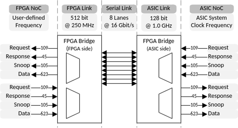
- REQUEST: Carries 109 bit of data for each NoC packet
- RESPONSE: Carries 45 bit of data for each NoC packet
- SNOOP: Carries 105 bit of data for each NoC packet
- DATA: Carries 623 bit of data for each NoC packet
These channels are muxed/demuxed by the C2C link onto an 8 lane serial link between the eProcessor ASIC and the companion FPGA. The C2C link is based on 16 Gb/s serial lanes with a combined bandwidth of 128 Gb/s per direction. These serial lanes use EXTOLL’s own PHY IP on the ASIC side, and Xilinx’ GTH Transceiver IP for FPGA implementations. The link can be configured for 4 or 8 lanes to support different use cases.
The figure below shows an example connection between an ASIC implementation and an FPGA implementation of the C2C, which is one use case within the eProcessor project.
The serial lanes use 128b130b encoding as well as scrambling to provide enough transitions for the clock data recovery in the PHY block. The C2C link wraps the NoC’s CHI packets into link packets for transmission, which include a CRC for error detection. On serial links, like the ones used here for the connection between eProcessor and the FPGA, bit errors are expected to happen sooner or later. To still ensure reliable data communication, the C2C link includes a link level retransmission. If a link receiver detects a CRC error, it requests a retransmission of this packet and all following ones from the opposite transmitter. Detected errors include things like:
- Line coding errors
- Protocol & framing errors
- Data consistency errors
- Remote errors, which can be ony of the above errors but detected by the link partner
The C2C link also utilizes credit based flow control to sustain the link bandwidth. The credits are used to ensure that the link partner has enough room to accept a packet before it is transmitted. Each receiver allocates a certain amount of storage for packets of each channel (Request, Response, Snoop, and Data). Then the amount of allocated space is communicated to the remote transmitter. The transmitter then checks the available storage space of the receiver before transmitting a packet, and only transmits a packet, if the receiver has enough storage space available. After the packet has been sent the storage space available to the transmitter is reduced according to the size of the sent packet. And once the receiver has forwarded the packet, and the storage space is available again, this is again communicated to the transmitter.
A data granularity of 128-bit is used for the link protocol to simplify the encoding and decoding of link packets, which also minimizes the link’s latency. Furthermore, the initialization of the link is executed automatically.
For the eProcessor project, the full HDL implementation and a UVM based verification of a 4 lane and 8 lane C2C was carried out for both a GF22 ASIC technology target and a Xilinx UltraScale Zync FPGA target.